
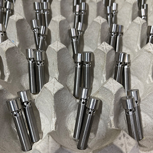
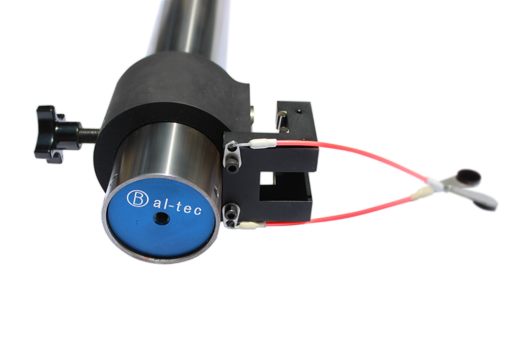
Custom Fine Adjustment Screw
Build your own Custom Fine Adjustment Screw.
We supply custom screws that utilize only the finest materials and feature complete customization with variable options for thread size, screw material, ball end material, size, and even include custom locking features in any quantity requested.
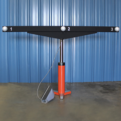
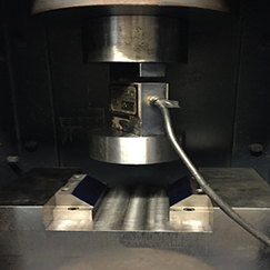
Condor Scale Bar
The Condor Scale Bar was designed specifically to make performing the ASTM E3125-17 simple. The ASTM Standard Test Method for Evaluating the Point-to-Point Distance Measurement Performance of Spherical Coordinate 3D Imaging Systems in the Medium Range, was released in December of 2017. Bal-tec was the supplier of Integration Spheres for the development of the standard. Shop Now

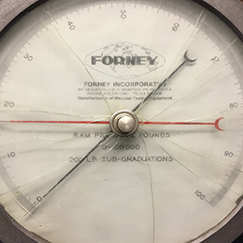
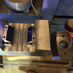
Combo Plate/Sphere Ranging Target
For a given instrument setting, the number of points on a target that is farther from the IUT is less than that for a target that is closer to the IUT. For a sphere target , this issue is exacerbated by the fact that the return intensity is not the same from all the locations on its surface. A return beam corresponding to lower return signal intensity may not register with the instrument , resulting in missing points from a sphere’s outer periphery (compared with data from the sphere‘s surface at the center). This reduces the coverage area of the scan data on a sphere at the farther location, compared with that at the nearer location (as illustrated in figure 9). This in turn increases the error when calculating the center of the sphere using a nonlinear least squares fitting algorithm. Shop Now
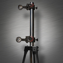
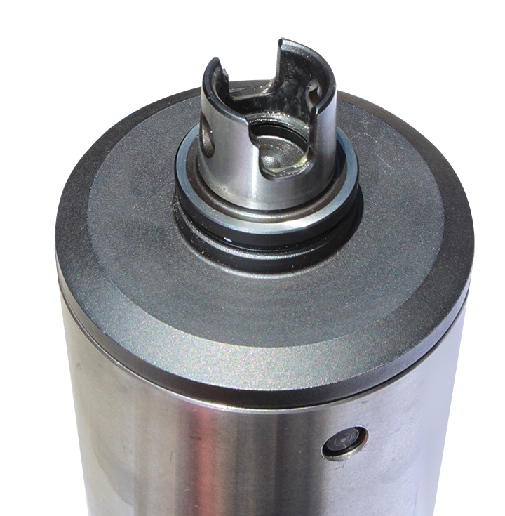
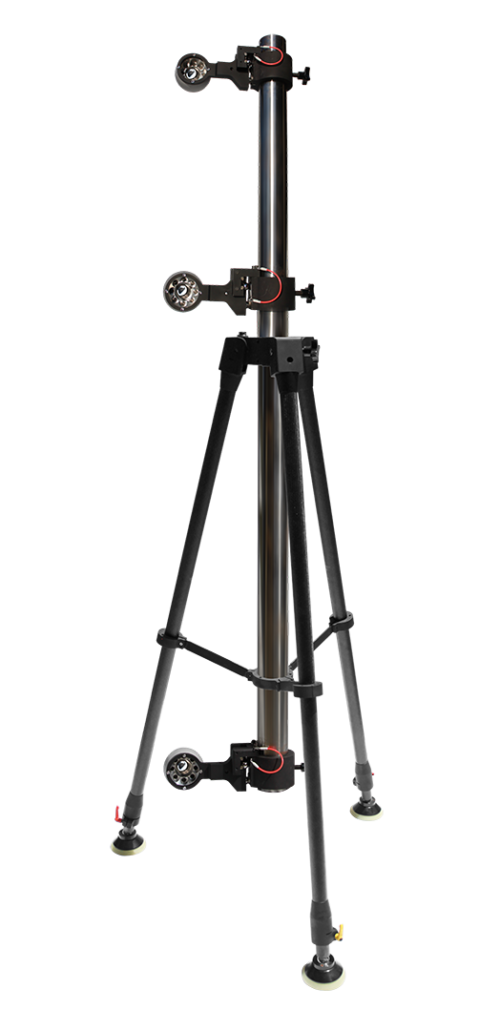
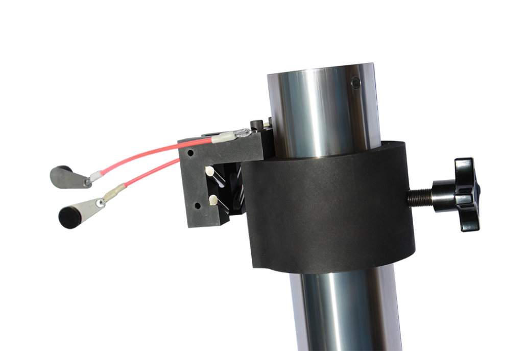
Tri-Integration Sphere Tower
Relative Range Tests – A relative range test is performed by placing the target at two positions (a near position and a far position), measuring the target at both positions with the IUT and the RI, and calculating the relative range error. If LruT and LRr are the distances between the targets as measured by the IUT and RI, respectively, then the relative range error (ERR) is given by: ERR = LruT – LR!. The RI in all the tests performed at NIST is a laser tracker, and the IUT is a laser scanner; however, the choice of instrument for RI is left to the user.
Depending on the design of the target, the relative range tests can be performed in one of two configurations. In the first configuration, both the RI and IUT are on the same side of the target (as seen in figure l); in the second configuration, they are on the opposite side of the target (as seen in figure 2). Alternative connfigurations were proposed and discussed by the subcommittee, but these two configurations offered lower uncertainties in obtaining the reference lengths.
The choice of the configuration depends on the procedure to obtain the derived point using the RI. It should be noted that the configuration in figure 1 yields a slightly greater uncertainty in determining the reference lengths, as the RI is not in line with the target positions. In such a configuration, errors associated with the angular encoders increase the reference length uncertainty. Even though the configuration in figure 2 offers lower uncertainty than the first configuration, it results in higher uncertainty for shorter lengths and lower uncertainty for longer lengths. This may be problematic, as the IUT will likely have tighter specifications for shorter lengths and wider specifications for longer lengths .
See gallery below.